

BIM and Revit
Our full-time BIM and Revit team works with CAD and site coordinators to combine the building services in 2D and 3D, then submits them for approval as shop drawings before installation.
Buildings modelled before they are built
SECCO uses intelligent 3D model-based design and construction on its building services work. We have implemented Revit software and hardware, with a full-time BIM and Revit team.
BIM gives a digital representation of the physical and functional characteristics of a building, and a shared source of information about it through its life cycle. We use BIM methods to manage design across the project and to improve delivery.
Building services modelled together
Revit is an application built for building information modelling, with features for architectural design, mechanical, electrical and plumbing (MEP) systems, and structural engineering and construction.
In a 3D model, ducts, pipes, cable trays and plant sit at their true size and position, so they can be checked against each other before anything is fixed on site.
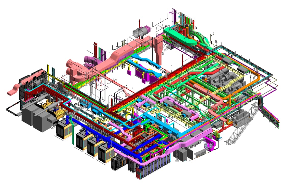
From separate systems to approved shop drawings
On a data centre, the power, data, UPS, automation, air-conditioning, fire-fighting, hydraulic and security systems are each designed to the owner's requirements. We combine them in CAD, 2D and 3D to catch obstacles, installation faults and sequencing problems before work starts on site.
What gets combined, and what we check
Systems combined on a data-centre project
- Main power supply
- Data and communication trays
- UPS and backup power
- Automation
- Air conditioning
- Fire fighting
- Hydraulics and sanitary
- Security
What each combination is checked for
- Installation sequence
- Installation space
- Work function
- System integration
- Service and access
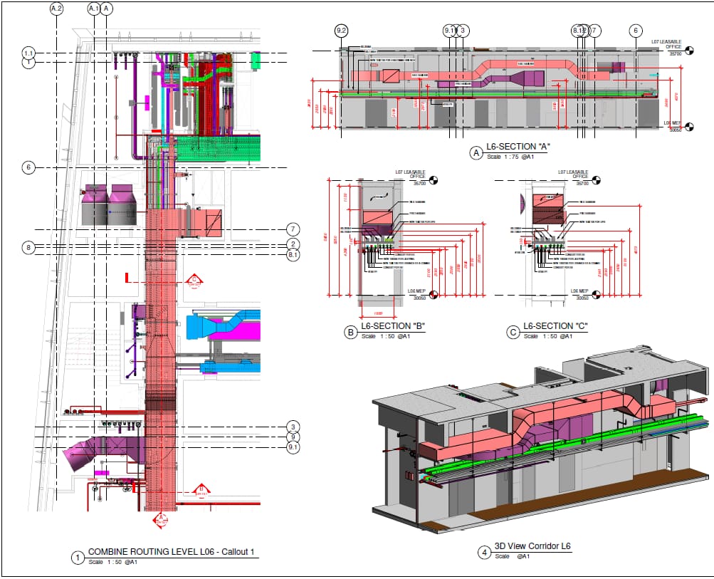
Combined routing in plan, section and 3D
Coordination sheets, like this one, show the combined routing of an area in plan, section and 3D. The combination is then submitted for approval and issued as shop drawings for installation.
Digital engineering on data-centre projects
For data-centre work we set up Autodesk Construction Cloud at the start, so integrated models and shop drawings are developed before construction begins.
Drawing review
Drawings reviewed and marked up on the platform, to reduce errors and miscommunication.
Model coordination
Every party works from synchronised, clash-free models.
Site inspection forms
Digital forms capture inspection data on site in real time and support compliance with safety standards.
Assets
Assets tracked through the project, from procurement onwards.
Quantity take-off
Quantities taken straight from the models, for faster and more accurate estimates.
Schedule integration
Primavera P6 schedules linked to the cloud platform, so planning lines up with the models in real time.
Talk to an engineer about your next building.
Tell us about the project, the programme and the systems you need. A SECCO engineer will reply.