

Data-centre capabilities
Power, cooling, fire protection, telecommunication, security and monitoring for data halls and office areas, built by one MEP contractor.
Every system a data hall depends on, under one contract
The systems in a data centre depend on each other. The chillers need power, the generators need their own fire protection, and the monitoring system has to see all of it. SECCO builds these systems as one MEP package, from the electricity supply to the chilled-water supply, including the ELV systems and backup power.
We design and build redundancy to the Uptime tier or TIA-942 requirements the operator sets, and we coordinate every system in one model before installation starts.
The data hall and the office area need different systems
We plan the data hall separately from the office area, which includes the network operations centre (NOC), because they serve very different loads.
Data hall
- Air conditioning: central chiller plant with CRAH or CRAC units along the hall
- Power supply: double source, UPS and PDUs
- Fire protection suited to live IT equipment
- Telecommunication, linked to the meet-me room (MMR) for incoming and outgoing connections
Office area and NOC
- Air conditioning: VRF or VRV units, ventilation and pressurisation
- Sanitary system
- Power supply
- Security system
- Fire protection system
Power that rides through a utility failure
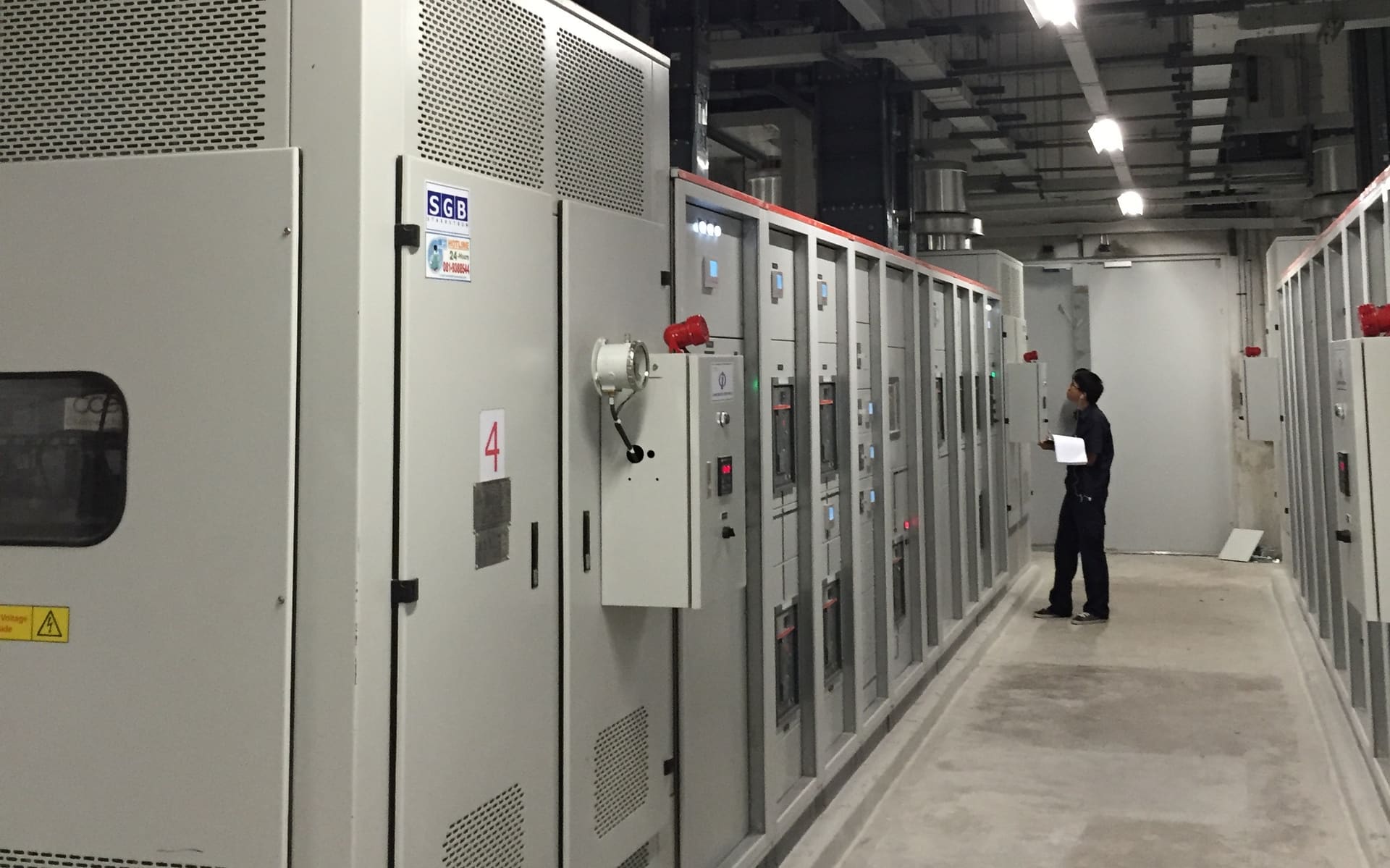
Data-hall power comes from a double source and runs through UPS systems and PDUs to the racks. A typical backup architecture behind it has two levels. The first is two independent medium-voltage feeders from separate substations, each with its own transformer substation, and automatic bus-tie transfer at the main distribution boards.
The second is an on-site diesel generator set on the emergency main distribution board, governed by the ATS controller. On total loss of utility voltage it starts automatically, with a design target of restoring power to the ATS bus within 10 to 15 seconds. It is rated to carry life-safety and mission-critical HVAC loads at full load.
- High-, medium- and low-voltage systems, UPS and emergency power
- Substations, transmission lines and underground cabling through our utilities work
- Switchboards set with clearance and service space, sequenced to the customer load
- Integration tests with the generators, and blackout tests that prove the transfer
Cooling from the chiller plant to the rack rows
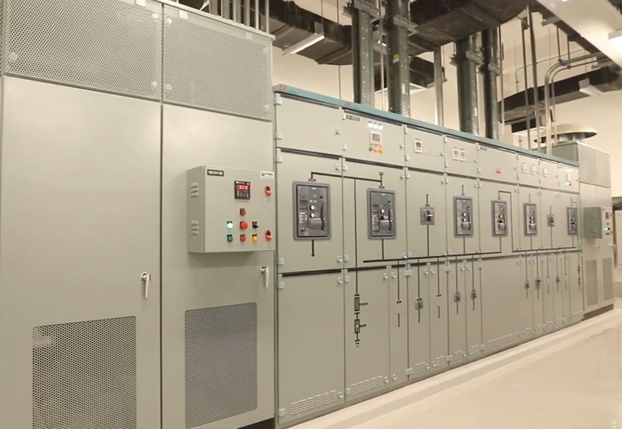
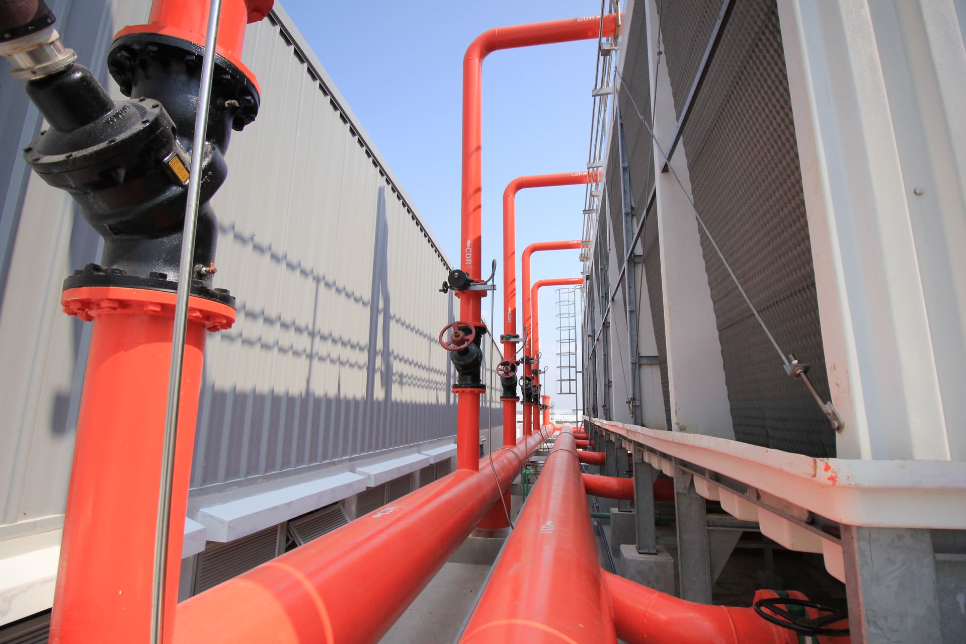
For the data hall we build central chilled-water plants: water-cooled chillers, pumps, cooling towers and, where the design includes them, thermal storage tanks. Chilled water feeds CRAH units in the hall, which take heat out of the air. The chillers pass that heat to the condenser water, and the cooling towers reject it outside.
The office area and NOC use VRF or VRV systems. We install the piping, leak- and pressure-test it with nitrogen, charge the refrigerant, set up the controls and test the system together with the BMS.
- Headers and branch pipes installed first, then chillers, pumps, valve groups and control devices
- Valves for future cooling towers installed while the cooling towers go in
- CRAH units connected to chilled-water, drainage and air-distribution ductwork
- Pressure and leak tests on each piping loop to specification
- Precision air, ventilation, pressurisation and energy management systems
Fire protection matched to each room
Different rooms in a data centre need different suppression. A graphic annunciator panel in the facility operations centre (FOC) gives centralised, real-time status of the fire systems.
Data hall
- Water mist: high-pressure micro-droplets that leave little liquid residue and limit thermal shock on live IT racks
Electrical equipment rooms
- Clean-agent gas suppression (Novec 1230) with zero ozone-depletion potential and a 10-second discharge
Battery, transformer and generator spaces
- Inert gas (IG-100, 100% nitrogen) for battery and transformer spaces, which suppresses fire by displacing oxygen
- CO2 total flooding for diesel generator enclosures and fuel bays
Whole building
- Fire alarm, fire protection and sprinkler systems
- FM200 clean-agent systems
- A fire incident case test of the full response sequence
Telecommunication, security and monitoring
BMS, CCTV and access control are installed to the same method: clarify points and locations, design the cabling, install and terminate, set addresses, then test each device, each function and the integration with other systems.
Telecommunication
- Meet-me room (MMR) for incoming and outgoing links to the data hall
- LAN, data communication and structured cabling systems
- Data and communication trays coordinated with every other service in the model
- Cabling to our quality-control rules: labelled addresses, no crossed wiring and separate conduits where interference must be contained
Security and access control
- CCTV with network video recorders and workstations
- Access-controlled doors and scanner devices, with control panels and workstations
- Integration tests between CCTV and access control
BMS and monitoring
- DDC panels, field devices and workstations
- Tested in stages: field command, software point, operation and integration tests
- Chiller plant management and energy management systems
- Integration tests with other systems, including VRF
Redundancy, in plain terms
SECCO designs and builds redundancy to the Uptime tier or TIA-942 requirements the operator sets. These are the terms those requirements use.
| Term | What it means |
|---|---|
| N | Exactly enough capacity to carry the load. Losing or servicing any unit reduces capacity. |
| N+1 | One more unit than the load needs, such as an extra chiller or UPS module, so any one unit can fail or be serviced. |
| 2N | Two complete, independent systems, each able to carry the whole load. An entire path can be lost or maintained. |
| Concurrently maintainable (Uptime Tier III) | Every component and distribution path can be taken out for planned maintenance without shutting down the IT load. |
| Fault tolerant (Uptime Tier IV) | The facility keeps the IT load running through any single unplanned failure of a component or path. |
Questions operators ask
Which redundancy level do you build to?
What design work does SECCO take on?
Who looks after the systems after handover?
Have you worked with international firms?
Where next
Planning a data centre? Talk to our data-centre team.
Tell us the stage, the location and the redundancy you need. A SECCO engineer will reply.